Veveakis + Review of Extremum Postulates Curr Opin Chem Eng 7 40e46
![]()
Solidification Morphology and Bifurcation Predictions with the Maximum Entropy Product Charge per unit Model
1
Department of Materials Science and Engineering, Academy of Republic of ghana, Legon, Accra P.O. Box LG 77, Republic of ghana
2
Department of Mechanical and Materials Engineering, University of Cincinnati, Cincinnati, OH 45221, The states
*
Author to whom correspondence should be addressed.
Received: 30 October 2019 / Revised: 16 December 2019 / Accustomed: xviii December 2019 / Published: 26 Dec 2019
Abstract
The use of the principle of maximum entropy generation per unit of measurement volume is a new approach in materials science that has implications for understanding the morphological development during solid–liquid interface growth, including bifurcations with or without diffuseness. A review based on a pre-publication arXiv preprint is outset presented. A detailed comparing with experimental observations indicates that the Maximum Entropy Product Charge per unit-density model (MEPR) can correctly predict bifurcations for dilute alloys during solidification. The model predicts a critical diffuseness of the interface at which a plane-forepart or any other form of diffuse interface volition become unstable. A farther confidence test for the model is offered in this article past comparing the predicted liquid improvidence coefficients to those obtained experimentally. A comparison of the experimentally adamant solute diffusion constant in dilute binary Lead–Sn alloys with those predicted by the various solidification instability models (1953–2011) is additionally discussed. A expert predictability is noted for the MEPR model when the interface diffuseness is small. In comparison, the more traditional interface break-downwardly models have low predictiveness.
one. Introduction
The maximum entropy generation principle [1,two,3,4,five,6,7,8,9,10,11,12,thirteen,14,fifteen,16] has brought significant predictive capability to quantitative materials scientific discipline. The principle has been able to reveal (a) the onset of various forms of morphological bifurcations during growth, particularly the onset of the start roughening transition [ane,ii,vi,9]; (b) circuitous solute segregation and texture reconfiguration phenomena, particularly noted during tribological contacts [4,12]; (c) Belousov–Zhabotinsky patterns and reaction pathways for high temperature reactions [2,3]; (d) the onset of steady country structures during solid–solid vesture [5,6,seven,8]; and (due east) the stable ellipsoidal patterns that are noted in solidification microstructures (dendrite tips), multiphase fluid flows, and particle sedimentation [2,10,11,12,xiii,fourteen,xv,16,17,eighteen,xix]. The principle accurately predicts the trajectory of objects in movement when subjected to a gravitational field [16] and by extrapolation of the field-theory for the assessment of the efficacy of solar cells [17].
The maximum entropy production rate-density, MEPR, or the Maximum Entropy Production Principle, MEPP, are the acronyms used in the literature [2,6,9,ten] for analyses that employ the entropy rate maximization principle. We have chosen to utilise MEPR [2] in this article to emphasize the importance of the "rate" in the acronym. A MEPR hypothesis is tested in this article for initiating interface diffuseness or topographical changes in the two-stage and/or diffuse interface regions. Whatsoever criterion for bifurcation based on this principle is expected to exist related to the limerick, division role, velocity of solidification, and the temperature slope experienced in the solid–liquid zone [1,2,eighteen].
The MEPR model postulates that the entropy generation is maximized for an interface transition (bifurcation) to a different configuration (i.eastward., to a different atomistic or topographical (morphological) variant). In this article, we first review the MEPR solidification bifurcation model [1,2] and compare it with other models for the airplane front instability. The model predictions are tested with the experimental data bachelor from published studies on numerous dilute binary alloys [ane]. The ensuing model for pure substance or a binary alloy has been shown to quantitatively predict the size of a diffuse interface and the number of pseudo-atomic layers present in the diffuse zone [one]. This is reviewed below. A further comparison with experimentally measured breakdown groupings of variables that take been reported in the solidification-research literature indicates that the MEPR model is also able to account for the interface topography every bit existence either of a faceted (f) or non-faceted (north/f) kind [1]. It must be noted that model also correctly offers a quantitative measure for the transition from facet to non-facet (f/nf) planar or to a non-planar topography, every bit being dependent on the velocity and the temperature slope [i]. Every bit the entropy generation is related to the gradients, it is possible that the MEPR criterion may likewise allow for a better approximate of the solute diffusion constant in binary alloys [18] that has proved elusive to predict by traditional models. This hypothesis is tested for dilute Atomic number 82–Sn alloys in this article.
When an alloy is directionally solidified at a low velocity (typically in the order of one micrometer per second), a planar morphology is start noted at the solid–liquid interface. With an increase in the transformation velocity (enabled by increasing the cooling rate or the Bridgman–Stockbarger imposed growth rate (See for case https://en.wikipedia.org/wiki/Bridgman-Stockbarger_technique), the initially planar interface becomes unstable with other shapes, transforming to a non-planar, macroscopically jagged or wavy cellular shape to the variations possible in the topography; or information technology may transform to a diffuse interface with non-planar shape variations [18]. There is a loss of work potential, WL, with a new shape or diffuseness formation, which in plow is related to the entropy generation. The advent of a smooth-cellular or jagged morphology from a planar interface, especially for binary alloys, depends on the material composition, CO (wt% or mole/yard3), velocity V (g/due south) of the growing interface, and the temperature slope ThousandL (K/1000) in the liquid and k, the non-dimensional solute partitioning coefficient. These variables at the point of morphological instability are commonly subscripted with the symbol (c) to bespeak a transition [18,19,20,21,22,23,24,25,26,27,28,29,thirty,31,32,33,34,35,36,37,38,39,40,41,42]. Various theoretical models [18,nineteen,xx,21,22,23,24,25,26,27,28,29,30,31,32,33,34] have been offered to explain the transition, however, the two nigh widely employed models (prior to MEPR) that describe the interface instability from planar to not-planar are the constitutional undercooling (Cutting) [19,xx,21,22,27] and the linear stability theory model (LST) [31]. A minimum–maximum entropy model was also previously proposed [24] but did not provide comprehensive predictability, ostensibly considering the Prigogine criterion used in that model for the minimum–maximum criterion was not applicative [2]. The objective of this commodity is to extend the conviction in the MEPR model with comparative tests made in [i] in order to select betwixt the models.
The CUT, LST, and MEPR models contain a diffusion parameter, namely, the coefficient of diffusion of solute in the liquid. Consequently, 1 additional exam for the comparison of the iii models is to compare the predicted values of the coefficient of improvidence to an experimental number measured from a not-solidification experiments at that temperature. In [18], information technology was shown that the values predicted past Cut and LST models evidence considerable difference from the experimental number. In this article, comparisons with the MEPR model are made.
2. The MEPR Model
During the ane dimensional solidification of a pure metal or a binary molten alloy, which is at freezing temperature under a stock-still temperature gradient and with constant interface velocity there is a loss of work potential from the dissipation of kinetic energy, giving rise to entropy generation rate density
(J m−3K−1s−ane) is given by [ane] in the region of the diffuse interface with dimensions
(yard). The subscript max. indicates that that the maximum value of this new entropy generation charge per unit is given past:
where Δρ thou (kgm−3) is the overall density shrinkage given by (ρ l Δρ/ρ southward), Δρ (kgm−three) is the density change from liquid to solid (ρ s − ρ l); ρ southward (kgm−3) and ρ l (kgm−3) are the densities of the fully solid and fully liquid zones, respectively. The symbol GSLI (Km−one) is the temperature slope beyond the solid–liquid interface, including the diffuse interface. This gradient is hard to mensurate experimentally, and so it is commonly approximated as the boilerplate between the rigorous-solid and rigorous-liquid regions. In this article, ChiliadSLI is causeless to be approximately equal to the temperature gradient in the fully liquid zone, ThouL (Km−1), (i.e., GrandSLI ≈ ML).
At the solid–liquid interface region, during directional solidification of a binary material, the existence of diffuseness or a non-planar morphology (such as cellular) can produce new entropy. Post-obit Sekhar [ii], the entropy rate maximization in this region when compared between various morphological pathways can be thought to be somewhat coordinating to the gratuitous energy selections between various phases. A cellular construction produces entropy of a positive value that increases with velocity, as does the planar diffuse construction [i,2], just at dissimilar rates. The postulate of MEPR applied to solidification morphology is that the highest entropy-rate-producing configuration is the almost stable. During directional solidification (one dimensional growth in casting, every bit is done for turbine blades or jewelry industry), the first transition from a stationary planar interface is the evolution in the interface region from an atomically sharp to a diffuse interface between the rigorous solid and the rigorous liquid [two]. For an alloy, further topographical variations become possible as the entropy generation rate per unit of measurement book reaches a peak, beyond which a cellular or other not-planar structure (e.k., cells or dendrites) tin can overtake the planar entropy production rate at any given composition of the alloy [1,2]. Detailed calculations for developing Equation (1) for the diffuseness dimension and the instability criterion are shown in [ane]—only a brief review is provided below. The maximum entropy generation rate per unit of measurement volume (or the entropy rate density) [i,2] is related to
Jm−threeYard−1south−ane), which is the entropy transfer rate from the solute slope in the liquid and
(Jm−iiiK−ones−1) (i.e., the main component of the entropy generation charge per unit that describes the entropy generated due to exchange of affair and heat in the SLI), expressed as:
and
are given by
and
, respectively [1]. The term ∆hsl (Jm−3) is the heat of fusion, which is an approximation for ∆hone thousand [ii]; ∆hm (Jmol−i) is the rut of fusion with defects; thouL (Kmthreemole−1) is the gradient of the liquidus line at the solid–liquid boundary for a binary material; k (dimensionless) is the partition coefficient that can be obtained from the binary phase diagram; DL (mtwodue south−1) coefficient of solute improvidence in the alloy. Here, ΔTO (One thousand) is the solidification temperature range, which is expressed as (T50 − Ts) or (CO(1 − yard) mL/k), where Tl and Tdue south are the liquidus and solidus temperatures, respectively, and can exist obtained from the phase diagram. The conditions given by Equations (3a) and (3b) below for a maximum or minimum defines a possible onset of a bifurcation condition (morphological instability).
or
Note that arguments to signal the maximization condition are provided in [two,6,9,x]. Annotation that
is negative when inferring a maximization condition. Although Tsi and Tli are unknown based on binary alloy materials, the thickness
of the diffuse interface (1000) can exist approximated for dilute solutions by assuming that Tsi ≈ Tm and Tli ≈ Tm, and following the procedures adult in [one], the standard solute balance at steady state growth forth with Equation (3a) in a higher place tin can used to yield:
Hither, CO (wt % or mole thousand−iii) is the solute concentration in the alloy.
Similarly, Equation (two) yields,
Now by using (3b) and (five),
tin can be written as:
where N (grandii M−iis−2) is defined every bit
, One thousand (kii K−iis−ii) is defined as
and B (m2 1000−iisouth−2) is divers every bit
.
Hither, yardeff is the effective segmentation coefficient for a diffuse interface. The equation is valid for extremely dilute alloys. Changing the formulation of Equation (six) by placing back into Equation (5) now also gives the driving force diffuseness for a binary alloy material as:
, where d is the interplanar lattice spacing normal to the growth direction. However, note that the exact bifurcation may occur at whatever velocity and temperature gradient greater than that set by Equation (5) (i.e., Equation (5) only sets i boundary condition). By analyzing the entropy generation density for a wavy interface [ane], 1 can also infer that the interface will break down between
This is the MEPR status for describing the breakdown limits. Because the condition is based on the comparing of the entropy charge per unit maximization, it may also be recast in terms of the cooling rate (VGSLI)C.
Annotation that Effigy 1 establishes a relationship between the diffuseness and the suspension downwards variable. Figure i shows the plot of the full diffuseness equally a office of (V/Gsli)c. The figure plots the ready of measurable breakup parameters. For any alloy this would be a straight line every bit per the MEPR model. However, nosotros annotation that that the ring is the like across various alloys thus highlighting the previously unanticipated relationship between interface diffuseness and the solidification parameters. This implies that the results shown below in Figure ii and Figure 3, namely the maximums in the entropy generation rate, are predictable past the experiments. Additionally, the slopes are dissimilar for faceted materials when compared to the non-facet situation, perchance indicating features of diffuseness not fully captured by the MEPR model.
Equation (half-dozen) can be related to the processing parameters for constrained or unconstrained solidification namely,
or the cooling rate (
respectively to yield the following entropy rate based criteria,
where c refers to critical and N is defined below Equation (6) (please also meet nomenclature).
Figure ii and Figure iii show the plot of the entropy charge per unit density equally a function of the blend parameters (diffuseness) and the processing and for the MEPR model. The beginning and second derivatives westward.r.t. to Five at abiding ζ and GSLI indicate that the entropy generation rate volition increase linearly with velocity unless solute partitioning into the liquid is allowed. When solute partitioning is possible, the entropy charge per unit generation term indicates a maximum when plotted as a part of velocity (Effigy two). If no other interface configuration is feasible (those that brandish a higher entropy rate generation, such as a seaweed, jagged or fine tip interface), the interface will remain planar during growth. Note that
cannot be less than cipher (second police force of thermodynamics). This implies that regardless of the sign of GSLI, the disquisitional
can merely have a lower value of nada for a planar interface. Thus, a not-planar shape can always overtake a plane front end morphology for a negative temperature slope, or in other words a negative temperature gradient volition always imply a breakdown into cells or other patterns (unless a high-velocity-airplane front transition occurs [two]). Additionally, because cellular shapes with a diffuse interface are seemingly restricted by the bounds of entropy from the diffuseness of alternating shapes, boosted configurational entropy production charge per unit increases for circuitous features (due east.g., dendrites) are feasible and then volition always emerge every bit an alternative structure unless a very wide lengthened interface topographies are possible with no partitioning. This is a possible explanation for why well-defined cellular features are not commonly noted in microstructures, such as atomized powders that solidify with a negative temperature gradient. Effigy 2 and Effigy 3 show the entropy generation charge per unit density as a function of various solidification features and collapsed parameters that are known to influence instability of a detail topography or morphology. Note the definitions of B, Yard, and N from Equations (iv)–(6) and the nomenclature. When B becomes greater than or equal to Thousand, then N is either goose egg or negative; consequently, the interface diffuseness becomes undefined. The maximum entropy generation rate density increases with the corresponding increase in diffuse interface thickness and falls only when the parameter B approaches 0.v M. The growth of the interface can be steady when N is greater than one. When the temperature slope is zero, the diffuse interface thickness becomes undefined, thus allowing geff to take on a high value closer to one. When B is equal to M, then Due north is zero, and ζ and
are both undefined. From the transition instability criterion defined above, the peak for
against velocity occurs when 1000/B (dimensionless) is equal to 2 (i.e., Yard/Due north0.5 ) is equal to
. Figure ii in [ane] shows the plot of the entropy generation rate as a function of the diffuseness. When G > B, then the number of pseudo-diminutive layers nowadays within the lengthened interface region is easily related to the driving force diffuseness in an almost linear mode [1]. Note that the deviation from linearity sets in at a lower 5/GSLI as the concentration increases. At the condition where 1000 ≥ North > 1, noted in Figure 2, a steady slope is observed, where the Five/ThouSLI ratio shows a stiff effect on the number of pseudo-diminutive-spacings [1]. As the condition for 1 > Due north > 0 is encountered, fifty-fifty a small change in the Five/ThouSLI ratio can lead to a rapid change in the number of pseudo-atomic spacings at the interface. Figure 3 shows the parabolic-like profile of the entropy generation rate density as a function of Five/Gsli. Both Figure ii and Figure 3 indicate that a peak is noted in the entropy generation rate density for a planar interface, essentially giving other entropy producing morphologies a possibility to dominate over the plane front construction (whether diffuse or not). An example is shown in Figure 3 of how the entropy rate for a cellular design or a dendritic morphology may bespeak transitions to those shapes. Note that an implication of the results in Figure 1 is that ΔTSLI approaches ΔTO, only a morphological transition prevents the full attainment for this separation for the plane front (i.e., if the high velocity plane front status is not encountered) [two,thirteen,38,39,40].
3. Traditional Instability Models
3.one. The Cutting Model
The first interface breakup model was proposed qualitatively by Rutter and Chalmers [22], and so quantitatively described by Tiller, Rutter, Jackson, and Chalmers [nineteen]. This model describes the interface instability (from planar to non-planar) every bit being enabled past a region of constitutionally undercooled liquid that forms ahead of the solid–liquid interface during growth from solute segmentation. For a binary alloy, the Cut criterion for instability is written equally:
where KL (Km−1) is the temperature gradient in the liquid, DL (10002s−1) is the solute diffusion coefficient in the liquid, and ΔTO (K) is the equilibrium solidification range (T50 − TDue south) for a liquid at composition CO (molem−iii). Also, Tl (K) and TDue south (K) are the equilibrium liquidus and solidus temperatures captured in equilibrium phase diagrams.
iii.two. The LST Model
In 1964, Mullins and Sekerka [31] proposed the linear stability model (LST) that considered the stability of a planar interface to a perturbation of an infinitesimal amplitude. In this stability model, the interface is unstable if any wavelength of a sinusoidal perturbation grows, and conversely the interface is stable if none of the perturbations can abound (regardless of their wavelength and surface free energy) tin grow. This LST criterion gives the instability criterion for a binary textile as:
where S (no units) is the Mullins–Sekerka stability constant [31], which is equal to ane for low velocities; ChiliadL and 1000Southward (J yard−1K−ones−one) are the thermal conductivities for the fully solid and the fully liquid states, respectively. Annotation that the Cut model in Equation (10) and LST model in Equation (11) converge for the limit of
.
A study by Burgeon et al. [38] with in situ interface imaging in microgravity conditions prevalent during the ordering of a cellular array structure concluded that the cause of interface dynamics and breakup are more than than just an account of the undercooled liquid alee of the interface. An experimental study past Inatomi et al. [39] also cast doubtfulness on whether an undercooled liquid or solute pile-up ahead of the interface is always present. They have argued persuasively that none of the theories for breakup may be correct. For an interface's topographical instability in the instance of facet prone materials, a strain accumulation model [34] has also been considered as describing the interface breakdown. Yet, Inatomi et al. [39] argue against a general strain model equally the cause for the instability. In reference 1, the variables ZCUT and ZLST were developed as parameters that draw the deviations from the experimental values. For the conditions where the interface instability occurs at high velocities, especially for very low alloy limerick materials or with very low temperature gradients [1], both the Cut and LST models lose even more predictive capability [1,18]. Additionally, it should be noted the CUT and LST models do not address the facet/non-facet transitions or diffuseness at a molecular level, which is easily treated by the MEPR model [1,2].
four. Comparing with Experiments for the Diffusion Coefficient Prediction
The experimentally reported values of DL from non-solidification experiments for Pb–Sn alloys at different concentrations are reported in [18] and are summarized in Table i. The experimental DL values shown in Table 1 directly measured from non-solidification experiments are corrected by an Arrhenius-type correction for the liquidus temperature if the report is at a higher temperature than the liquidus [30,31,32,33,34,35,36,37,38,39,40]. Yet, note that these corrected numbers but impact the results in a pocket-sized mode for the dilute alloy compositions considered. The results shown in Table 1 for the DL predictions for both Cut and LST show consequent and significant deviation from experimental measurements, as pointed out by De Cheveigne et al. [26] and Bensah et al. [eighteen]. From Table ane, we notation that the MEPR model shows stronger predictive capability of DL compared to Cut and LST for Pb–Sn alloys when compared with experimental values. Still, even with the MEPR model, large deviations are noted for experimental conditions with a small temperature gradient. Pb–Sn alloys are known to have very wide diffuse interfaces [1,21,35,36,37]. A lower GSLI dramatically influences the diffuse interface as noted in a higher place, and consequently the partition coefficient. The expectation that grandeff approaches one with increased interface diffuseness is a reasonable assumption for dilute Pb–Sn and icosahedral alloys with a diffuse interface [32,33,40,41,42,43,44,45,46,47,48]. Should keff, therefore, change from 0.636 to 0.95 considering of the depression temperature slope and diffuse interface, the DL value that is calculated is shown to become much lower to match the experimental data for even these depression solidification temperature- gradient experiments. The corrected values are also shown in italics in Table 1 in the highlighted office of the table. Regardless, it should be noted that the assumed change in keff to 0.95 is capricious and is only set to this number to illustrate the influence of the partition office on the calculated number.
v. Summary Discussions
Topographical and diffuse interface reconfigurations occur with a modify in the solidification rate. In this article, we pursue the hypothesis that the interface configuration during solidification is determined by the maximum rate of entropy product in the region between a rigorous solid and rigorous liquid phase. We posit that when an interface begins to migrate, in that location are several stable configurations that are possible. These include atomically planar, lengthened-planar, facet non-planar, and cellular nonplanar configurations. The configuration and topographical condition that affords the maximum entropy production charge per unit (MEPR) yields the well-nigh stable interface configuration. The principle of MEPR is applied to (one) describe atomically smooth and diffuse interfaces, (two) provide quantitative results for the diffuse interface thickness and the number of pseudo-atomic layers in the interface region, and (3) predict the transition from planar to a non-planar facet or non-facet cellular morphology equally a function of solidification velocity or temperature gradient. The MEPR model provides for an cess of the interface diffuseness at the breakup condition. It besides allows for the break down condition to be expressed in terms of the cooling rate and the entropy generation charge per unit.
Numerous experimental investigations spanning lx years have failed to comprehensively validate whatsoever of the existing solid–liquid interface (SLI) growth instability models. With the MEPR model for the first time, breakdown conditions are predicted with a fair caste of accuracy for several binary alloys, where no previous theoretical model had predictability. The model considers steady-land solidification at shut-to-equilibrium and far-from-equilibrium weather condition. For dilute Atomic number 82–Sn alloys, the MEPR model gives closer DL predictions compared to the predictions made past the more traditional Cutting and LST models. Regardless of the success of the model to date, it should exist noted that the model remains untested for alloys with a significant amount of solute content.
Author Contributions
Conceptualization, J.A.S.; methodology, J.A.Due south.; validation, Y.D.B. and J.A.S. formal analysis, Y.D.B. and J.A.South.; investigation, Y.D.B. and J.A.S.; resource, Y.D.B. and J.A.S.; information curation, Y.D.B.; writing—original draft preparation, Y.D.B. and J.A.South.; writing—review and editing, J.A.S.; visualization, Y.D.B.; supervision, J.A.Southward.; project administration, J.A.S.; funding acquisition, J.A.S. All authors have read and agreed to the published version of the manuscript.
Funding
The authors gratefully admit support from MHI Inc., www.mhi-inc.com Cincinnati, Ohio for this ongoing research.
Conflicts of Interest
The authors declare no conflict of interest.
Classification and Abbreviations
| Alphabetic character symbols | |
| Af | surface area of a solute flux in a liquid (mii) |
| ASLI | area of an interface in a solid–liquid region (mii) |
| B | Entropic contribution from the solute boundary layer |
| Cp | average heat capacity across a solid–liquid interface (Jm−3K−1) |
| d | interplanar lattice spacing (one thousand) |
| modify in concentration at a solute distance z (mole k−3) | |
| D | Diffusion Coefficient (grandiis−i) |
| fs | fraction of liquid solidified at the solid–liquid interface (dimensionless) |
| GS | temperature gradient in a solid (Km−1) |
| Thousand50 | temperature gradient in a liquid (Km−1) |
| GSLI | linear temperature slope across a diffuse interface (Km−ane) |
| Δhm | heat of fusion of a solid with defects (Jm−iii) |
| Δhsl | equilibrium oestrus of fusion (Jm−3) or (Jmol−one) |
| Js | solute flux in a liquid entering a solid–liquid interface (mole s−ane) |
| k | equilibrium partitioning coefficient obtained from the phase diagram (dimensionless) |
| keff | effective partition coefficient at a solid–liquid interface (dimensionless) |
| ΔKE | gain or loss in kinetic energy (J) |
| KL | thermal conductivity for a rigorous liquid (Jm−1K−1s−1) |
| KS | thermal electrical conductivity for a rigorous solid (Jm−one1000−isouthward−1) |
| 100050 | slope of the equilibrium liquidus line at the SLI for a binary cloth (Km3mole−1) |
| Thousand | Entropic contribution from the thermal menstruum |
| Northward | Diffuseness contribution to the entropy generation |
| Q | lost piece of work potential from the heat generation from a solid–liquid interface (J) |
| Ryard | molar gas constant (Jmol−1 Thou−1) |
| S | Mullins and Sekerka stability constant (dimensionless) |
| Due southf | flux entropy rate (JK−1due south−1) |
| entropy generation density due to solute gradient in a liquid (Jm−3G−ane) | |
| entropy generation density due to solute gradient in a solid (Jm−3K−1) | |
| change in entropy generation charge per unit density due to exchange of matter and energy to and from a solid–liquid interface with its surrounding (Jm−3Grand−ones−1) | |
| irreversible entropy generation charge per unit in a diffuse region (JK−onesouth−one) | |
| rate of entropy inbound a control volume (JK−1s−1) | |
| charge per unit of entropy leaving a control volume (JK−1southward−1) | |
| total irreversible entropy generated rate density at an interface (Jm−3K−1) | |
| entropy generation rate density by the solute gradient in a liquid (Jm−threeK−1) | |
| (𝑆𝑔𝑒𝑛)𝑚𝑎𝑥 | maximum entropy generation due to lost piece of work (JK−1) |
| 𝑑𝑆𝑐𝑣⁄𝑑𝑡 | total steady land entropy rate in a control volume (JK−anesouth−1) |
| 𝑑𝑠𝑐𝑣⁄𝑑𝑡 | total steady state entropy rate density in a control volume (Jm−1Grand−1south−ane) |
| t | time (s) |
| Tli | liquidus temperature at a solid–liquid interface purlieus (Thou) |
| Tsi | solidus temperature at a solid–liquid interface boundary (Yard) |
| ΔTSLI | temperature difference across a solid–liquid interface (One thousand) |
| (𝑑𝐶𝐿𝐺⁄𝑑𝑧) or (𝛥𝐶𝑂⁄𝛿𝑐) | alter in solute gradient in a liquid (mole chiliad−4) |
| Tm | melting temperature (K) |
| Tav | average temperature between Tli and Tsi across a diffuse interface (K) |
| ΔTO | solidification temperature range (Grand) |
| V | solidification interface velocity (ms−1) |
| WL | lost work (J) |
| dz or δc | change in the position length of the solute (1000) |
| ZCUT | difference parameter of Cut from experiment at breakdown (dimensionless) |
| ZLST | divergence parameter of LST from experiment at breakdown (dimensionless) |
| Greek symbols | |
| Ωf | flux volume (yardiii) |
| ΔΩS | volume shrinkage (10003) |
| Solute purlieus layer at the critical bespeak (1000) | |
| |Δρk| | density shrinkage (kgm−3) (ρdue south- ρl) |
| ρfifty | density of rigorous liquid (kgm−3) |
| ρs | density of rigorous solid (kgm−3) |
| Δμc | Chemical potential difference (Jmole−one) |
| ζ | solid–liquid interface thickness (1000) |
| ωD | energy of defects (Jm−3) |
| ΩSLI | volume of a solid–liquid interface (m3) |
| maximum entropy generation rate density for a moving interface (Jm−iiiG−is−ane) | |
| ηK | driving force diffuseness (dimensionless) |
| ηT | total diffuseness (dimensionless) |
| 𝜂𝛼 | thermal diffuseness (dimensionless) |
| Subscripts and acronyms | |
| CUT | ramble undercooling theory circa 1953 |
| LST | linear stability theory circa 1964 |
| MEPR | maximum entropy production rate circa 2011 |
| L | liquid |
| Due south | solid |
| LG | solute gradients in the liquid |
| SG | solute gradients in the solid |
| SLI | solid–liquid interface |
| HD | mean oestrus dissipation at the solid–liquid interface |
| f | facet |
| nf | non-facet |
| Expt | experiment |
References
- Bensah, Y.D.; Sekhar, J.A. Interfacial instability of a planar Interface and diffuseness at the solid-liquid interface for pure and binary materials. arXiv 2016, arXiv:1605.05005. [Google Scholar]
- Sekhar, J.A. The description of morphologically stable regimes for steady state solidification based on the maximum entropy production rate postulate. J. Mater. Sci. 2011, 46, 6172–6183. [Google Scholar] [CrossRef]
- Sekhar, J.A.; Li, H.P.; Dey, Chiliad.K. Belousov–zhabotinsky nano-bands and nanoparticles. Acta Mater. 2010, 58, 1056–1073. [Google Scholar] [CrossRef]
- Gershman, I.; Mironov, A.; Podrabinnik, P.; Kuznetsova, East.; Gershman, East.; Peretyagin, P. Relationship of secondary structures and wear resistance of antifriction aluminum alloys for journal bearings from the point of view of self-organization during friction. Entropy 2019, 21, 1048. [Google Scholar] [CrossRef]
- Nosonovsky, M.; Bhushan, B. Thermodynamics of surface degradation, self-organisation and cocky-healing for biomimetic surfaces. Philos. Trans. R. Soc. A 2009, 367, 1607–1627. [Google Scholar] [CrossRef]
- Martyushev, Fifty.M.; Seleznev, 5.D.; Kuznetsova, I.E. Awarding of the principle of maximum entropy production to the analysis of the morphological stability of a growing crystal. Zh. Eksp. Teor. Fiz. 2000, 118, 149. [Google Scholar]
- Bensah, Y.D.; Li, H.P.; Sekhar, J.A. The sgen rate maximization postulate: Applications to process-path assay for solidification and micropyretic synthesis. Cardinal Eng. Mater. 2012, 521, 79–86. [Google Scholar] [CrossRef]
- Nosonovsky, M. Cocky-system at the frictional interface for light-green tribology. Philos. Trans. R. Soc. A 2010, 368, 4755–4774. [Google Scholar] [CrossRef]
- Martyushev, Fifty.Grand.; Seleznev, 5.D. Maximum entropy production: Application to crystal growth and chemical kinetics. Curr. Opin. Chem. Eng. 2015, 7, 23–31. [Google Scholar] [CrossRef]
- Veveakis, Due east.; Regenauer-Lieb, K. Review of extremum postulates. Curr. Opin. Chem. Eng. 2015, 7, xl–46. [Google Scholar] [CrossRef]
- Poinsot, Fifty. Théorie Nouvelle de la Rotation des Corps; Bachelier: Paris, France, 1834. (In French) [Google Scholar]
- Sekhar, J.A. Tunable coefficient of friction with surface texturing in materials applied science and biological systems. Curr. Opin. Chem. Eng. 2018, 19, 94–106. [Google Scholar] [CrossRef]
- Chung, B.J.; Vaidya, A. Not-equilibrium pattern selection in particle sedimentation. Appl. Math. Comput. 2011, 218, 3451–3465. [Google Scholar] [CrossRef]
- Hill, A. Entropy Production as The Selection Dominion Betwixt Different Growth Morphologies. Nature 1990, 348, 426–428. [Google Scholar] [CrossRef]
- Wang, W.; Zhang, Y.; Liu, J.; Wu, Z.; Li, B.; Sundén, B. Entropy generation analysis of fully adult turbulent heat transfer flow in inward helically corrugated tubes. Numer. Oestrus Transf. A-Appl. 2018, 73, 788–805. [Google Scholar] [CrossRef]
- Ziegler, H.; Wehrli, C. On a principle of maximal rate of entropy production. J. Not-Equilib. Therm. 1978, 12, 229. [Google Scholar] [CrossRef]
- Patela, R. Engineering Thermodynamics of Thermal Radiation for Solar Ability Utilization; McGraw Hill: New York, NY, USA, 2010. [Google Scholar]
- Bensah, Y.D.; Sekhar, J.A. Morphological assessment with the maximum entropy production rate postulate. Curr. Opin. Chem. Eng. 2014, 3, 91–98. [Google Scholar] [CrossRef]
- Tiller, W.A.; Jackson, K.A.; Rutther, J.W.; Chalmers, B. The redistribution of solute atoms during the solidifications metals. Acta Met. 1952, 1, 428. [Google Scholar] [CrossRef]
- Walton, D.; Tiller, W.A.; Rutter, J.West.; Winegard, W.C. Instability of a smoothen solid-liquid interface during solidification. J. Met. AIME Trans. 1955, 205, 1023–1026. [Google Scholar] [CrossRef]
- Winegard, West.C.; Chalmers, B. Supercooling and dendritic freezing in alloys. Trans. Am. Soc. Met. 1955, 47, 463–468. [Google Scholar]
- Ruther, J.W.; Chalmers, B. A prismatic substructure formed during solidification of metals. Can. J. Phys. 1953, 31, 15–39. [Google Scholar] [CrossRef]
- Sato, T.; Kenji, I.; Ohira, Grand. Interfacial stability of planar solid-liquid interface during unidirectional solidification of Al–Zn alloy. Trans. Jpn. Inst. Met. 1980, 21, 441–448. [Google Scholar] [CrossRef]
- Kirkaldy, J.Southward. Entropy criteria applied to blueprint selection in systems with free boundaries. Met. Trans. A 1985, 16, 1781–1796. [Google Scholar] [CrossRef]
- Noel, Northward.; Jamgotchian, H.; Billia, B. In situ real-time observation of the formation and dynamics of a cellular interface in a succinonitrile-0.5 wt% acetone alloy directionally solidified in a cylinder. J. Cryst. Growth 1997, 181, 117–132. [Google Scholar] [CrossRef]
- De Cheveigne, S.; Guthmann, C.; Kurowski, P. Directional solidification of metallic alloys: The nature of the bifurcation from planar to cellular interface. J. Cryst. Growth 1988, 92, 616–628. [Google Scholar] [CrossRef]
- Tiller, W.A.; Rutter, J.W. The effect of growth conditions upon the solidification of a binary alloy. Can. J. Phys. 1956, 34, 96–121. [Google Scholar] [CrossRef]
- Shibata, G.; Sato, T.; Ohira, G. Morphological stabilities of planar solid-liquid interfaces during unidirectional solidification of dilute Al–Ti and Al–Cr alloys. J. Cryst. Growth 1978, 44, 419–434. [Google Scholar] [CrossRef]
- Morris, I.R.; Winegard, W.C. The evolution of cells during solidification of a dilute Lead-Sb alloy. J. Cryst. Growth 1969, 5, 361–375. [Google Scholar] [CrossRef]
- Sato, T.; Ohira, 1000. The cellular breakdown of the planar interface in unidirectional solidification of Al–Cu blend. Trans. Jpn. Inst. Met. 1971, 12, 285–294. [Google Scholar] [CrossRef]
- Mullins, Due west.W.; Sekerka, R.F. Stability of a planar interface during solidification of a dilute binary alloy. J. Appl. Phys. 1964, 35, 444–451. [Google Scholar] [CrossRef]
- Trivedi, R.; Kurz, W. Dendritic growth. Int. Mater. Rev. 1994, 39, 49–74. [Google Scholar] [CrossRef]
- Kurz, Due west.; David, J.F.; Rohit, T. Progress in modelling solidification microstructures in metals and alloys: Dendrites and cells from 1700 to 2000. Int. Mater. Rev. 2019, 64, 311–354. [Google Scholar] [CrossRef]
- Dey, North.; Sekhar, J.A. Interface configurations during the directional growth of salol-I. morphology. Acta Met. 1993, 41, 409–424. [Google Scholar] [CrossRef]
- Radojevic, 5.; Nikolic, Southward.; Valcic, A. Interface shape and distribution of solute during vertical bridgeman growth of Al–Cu alloy. Mater. Lett. 2002, 52, 248–254. [Google Scholar] [CrossRef]
- Fornaro, O.; Palacio, H.A.; Biloni, H. Segregation substructures in dilute Al–Cu alloys directionally solidified. Mater. Sci. Eng. A 2006, 417, 134–142. [Google Scholar] [CrossRef]
- Grange, G.; Jourdan, C.; Gastaldi, J. In situ ascertainment of synchrotron white beam X-ray topography of the solidification microstructures of an Al-0.73wt% Cu Alloy. J. Cryst. Growth 1992, 121, 315–321. [Google Scholar] [CrossRef]
- Bergeon, N.; Tourret, D.; Chen, L.; Debierre, J.Thousand.; Guerin, R.; Ramirez, A.; Billia, B.; Karma, A.; Trived, R.I. Spatiotemporal dynamics of oscillatory cellular patterns in three-dimensional. Phys. Rev. Lett. 2013, 110, 1–5. [Google Scholar] [CrossRef]
- Inatomi, Y.; Ashida, M.; Sakata, K.; Okutani, T. Simultaneous measurement of temperature and concentration during faceted cellular array growth under microgravity. World J. Eng. 2014, eleven, 41–48. [Google Scholar] [CrossRef]
- Sekhar, J.A.; Rao, P.V.; Trivedi, R. An icosahedral phase in the Lead-Bi system. Scr. Metall. 1987, 21, 543–547. [Google Scholar] [CrossRef]
- Rao, P.5.; Sekhar, J.A. Lattice parameter measurements on apace pressurized Sn-Pb alloys. Mater. Lett. 1985, iii, 216–218. [Google Scholar] [CrossRef]
- Sekhar, J.A.; Mantri, A.Southward.; Saha, Southward.; Balamuralikrishnan, R.; Rama Rao, P. Photonic, depression-friction and antimicrobial applications for an ancient icosahedral/quasicrystalline nano-composite bronze alloy. Trans. Indian Inst. Met. 2019, 72, 2105–2119. [Google Scholar] [CrossRef]
- Flemings, M.C. Solidification Processing; McGraw-Hill: New York, NY, United states of america, 1974; Chapter 8. [Google Scholar]
- Sekhar, J.A. Evolution of solidification microstructures at high interface velocities. J. Cryst. Growth 1991, 109, 113–119. [Google Scholar] [CrossRef]
- Burton, W.Yard.; Cabrera, N.; Frank, F. The growth of crystals and the equilibrium structure of their surfaces. Philos. Trans. R. Soc. A 1951, 243, 299–358. [Google Scholar] [CrossRef]
- Cahn, J.West.; Hilliard, J.Due east. Energy of a nonuniform system I. Interface free energy. J. Chem. Phys. 1958, 28, 258–267. [Google Scholar] [CrossRef]
- Landau, L. On the theory of phase transitions. Ukr. J. Phys. 1937, 11, 19–32. [Google Scholar] [CrossRef]
- Jackson, K.A.; Uhlmann, D.R.; Hunt, J.D. On the nature of crystal growth from the melt. J. Cryst. Growth 1967, 1, ane–36. [Google Scholar] [CrossRef]
Figure 1. The plot shows measured experimental conditions at breakdown in the abscissa and calculated interface diffuseness on the ordinate. If the total interface diffuseness is greater than one or two atomic layers, and so there is a possibility of not-facet morphology at breakup, otherwise it should be facet morphology [one]. The human relationship between total diffuseness and the ratio of the velocity/temperature gradient (V)C/(GSLI)C should yield a direct line irrespective of fabric parameters for any growth direction (or crystal plane spacing normal to a growth direction) in the MEPR model. The values V and GSLI are experimentally measured numbers at breakdown, and ηT is calculated from the model [ane]. Note that succinonitrile (SCN) alloys are non-faceted by an boosted thermal and possibly rotational diffuseness at the melting temperature, which makes the SCN material transformation always announced with a non-faceted morphology particularly when observed at optical level magnifications. Experimentally, the materials shown below the dashed line (log10 ηT = 2) are recorded to be macroscopically faceted [1]. For the zone for facet materials, a different gradient than in the non-facet region may stand for different mechanisms for growth (e.g., nucleation-dominated or dislocation-dominated) [22,32,43].
Figure 1. The plot shows measured experimental conditions at breakdown in the abscissa and calculated interface diffuseness on the ordinate. If the total interface diffuseness is greater than one or two atomic layers, then there is a possibility of non-facet morphology at breakdown, otherwise it should be facet morphology [1]. The human relationship between total diffuseness and the ratio of the velocity/temperature gradient (V)C/(KSLI)C should yield a direct line irrespective of cloth parameters for any growth direction (or crystal plane spacing normal to a growth management) in the MEPR model. The values V and ThousandSLI are experimentally measured numbers at breakup, and ηT is calculated from the model [1]. Note that succinonitrile (SCN) alloys are non-faceted by an additional thermal and perhaps rotational diffuseness at the melting temperature, which makes the SCN textile transformation always announced with a non-faceted morphology particularly when observed at optical level magnifications. Experimentally, the materials shown below the dashed line (log10 ηT = two) are recorded to be macroscopically faceted [1]. For the zone for facet materials, a unlike slope than in the non-facet region may represent different mechanisms for growth (e.g., nucleation-dominated or dislocation-dominated) [22,32,43].
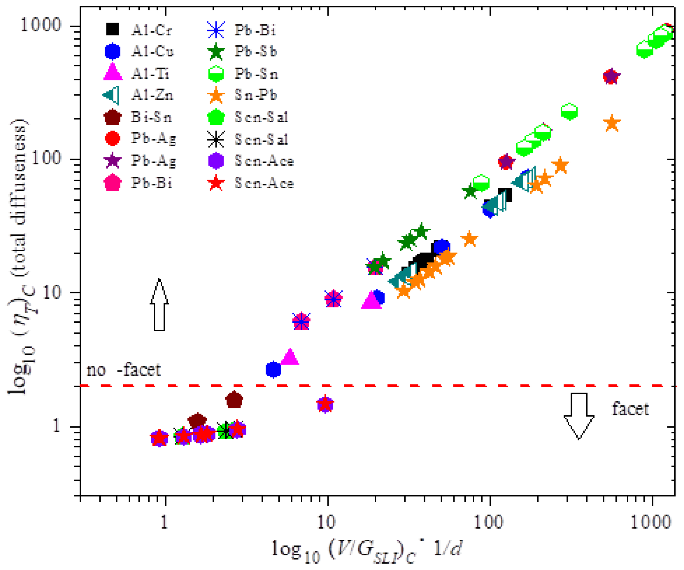
Figure 2. MEPR model prediction of the calculated maximum entropy generation rate density
(J/m3Ks) against the diffuse interface thickness at a abiding solute concentration for dilute binary materials. The
for the diffuse plane front end reaches its highest value at the summit of the bend (i.e., when M becomes equal to 2B).
Figure 2. MEPR model prediction of the calculated maximum entropy generation rate density
(J/m3Ks) confronting the diffuse interface thickness at a constant solute concentration for dilute binary materials. The
for the diffuse plane front reaches its highest value at the elevation of the curve (i.e., when M becomes equal to 2B).
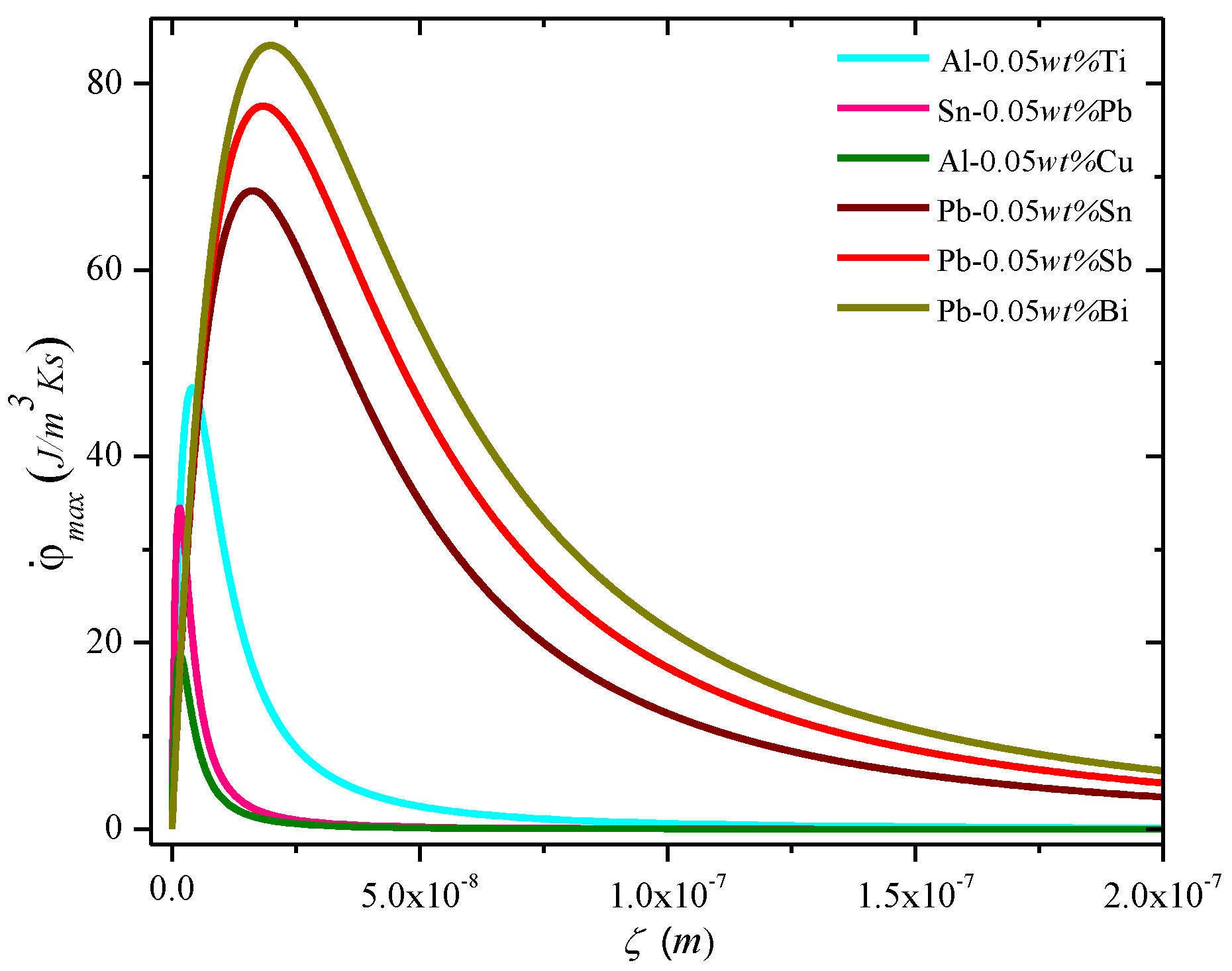
Figure three. MEPR model prediction [1] of calculated
(J/m3Ks) as a role of the (Five/GSLI) for Al–Cu with solute concentrations for five compositions (thick colored curves). The
increases with decreasing solute concentration and reaches a maximum value. At extremely low solute concentration, the binary fabric behaves similarly to a pure material (linear dark line) and
increases indefinitely with V/GSLI, like a pure metallic [i]. Note the two sparse schematic lines, ane for cells (that begins at the origin) and the other for some form of dendrites, are also shown to indicate how a bifurcation transition may be reached, and further how dendrites can overtake cellular morphologies (see reference [2] for more than details on types of dendrites). Note that in Equation (8) a similar graphical human relationship for the entropy rate density generation density is seen when the abscissa is the cooling rate (V∗YardSLI) [one]. For unconstrained dendrites [18] the cooling rate is a preferred grouping of processing variables to indicate peculiarly the fineness of the secondary dendrites with increased cooling charge per unit [32,33,43,44].
Figure three. MEPR model prediction [1] of calculated
(J/10003Ks) every bit a function of the (5/GSLI) for Al–Cu with solute concentrations for five compositions (thick colored curves). The
increases with decreasing solute concentration and reaches a maximum value. At extremely low solute concentration, the binary cloth behaves similarly to a pure fabric (linear dark line) and
increases indefinitely with V/GSLI, like a pure metal [i]. Note the two thin schematic lines, one for cells (that begins at the origin) and the other for some form of dendrites, are also shown to point how a bifurcation transition may be reached, and further how dendrites can overtake cellular morphologies (encounter reference [2] for more details on types of dendrites). Annotation that in Equation (8) a similar graphical relationship for the entropy rate density generation density is seen when the abscissa is the cooling rate (V∗ThousandSLI) [ane]. For unconstrained dendrites [eighteen] the cooling rate is a preferred group of processing variables to bespeak peculiarly the fineness of the secondary dendrites with increased cooling rate [32,33,43,44].
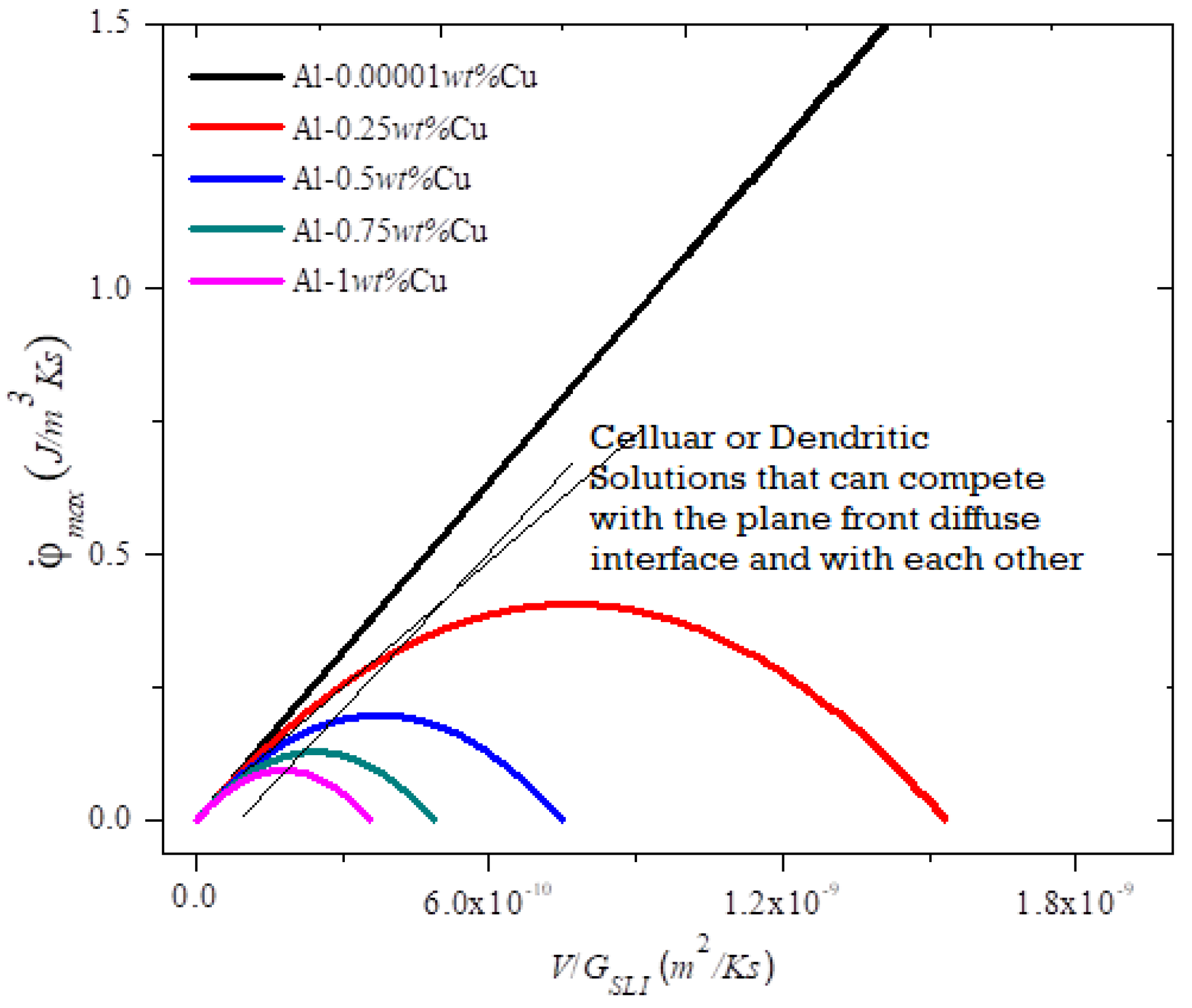
Table one. A summary of results for DL in instability atmospheric condition for experimental breakdown compared with the value obtained from three instability models. Note that for MEPR, MSLI was assumed to be equal to KFifty for the calculations. The diffusion data and physical constant from [eighteen] for Atomic number 82–Sn alloys is Ks = 33.vi (J/mKs), GrandL = 15.4 (J/mKs); the equilibrium partition coefficient is one thousand = keff = 0.636, Tm = 600.65 Chiliad, Δhsl = ii.48 × xeight (J/miii). The shaded cells contain values of DL (in italics) for both cases (i.eastward., the equilibrium segmentation ration too as when chiliadeff increases to 0.95 for the low temperature gradient conditions). MEPR Model: Circa 2011; LST Model: Circa 1964; CUT Model: Circa 1953.
Tabular array one. A summary of results for DL in instability conditions for experimental breakdown compared with the value obtained from three instability models. Note that for MEPR, GSLI was assumed to be equal to ThousandFifty for the calculations. The diffusion data and physical constant from [18] for Lead–Sn alloys is Ks = 33.vi (J/mKs), K50 = 15.4 (J/mKs); the equilibrium partition coefficient is k = keff = 0.636, Tm = 600.65 Thou, Δhsl = 2.48 × x8 (J/kiii). The shaded cells contain values of DL (in italics) for both cases (i.e., the equilibrium partition ration every bit well every bit when meff increases to 0.95 for the low temperature gradient weather). MEPR Model: Circa 2011; LST Model: Circa 1964; CUT Model: Circa 1953.
| Composition | DFifty (×10−9 m2/s) at Tl from Experiment * | Imposed | Variable | Alloy | Variable | k = 0.636 k = 0.95 | DFifty (×10−nine m2/south) at TS from Solidification Theories | ||
|---|---|---|---|---|---|---|---|---|---|
| VC (m/southward) ×10−6 | GFifty (M/m) | Ts (K) | Tl (K) | MEPR Model Lower Jump | MEPR Model Upper Jump | CUT Model | LST Model | ||
| Lead-0.01 wt% Sn | 1.656 | 167 | 540 | 600.621 | 600.604 | iv.619 | 2.3095 | 5.398 | 8.587 |
| Lead-0.03 wt% Sn | i.655 | 73.5 | 820 | 600.560 | 600.508 | iv.016 | 2.008 | iv.692 | 7.465 |
| Pb-0.05 wt% Sn | one.654 | 73.v | 1380 | 600.499 | 600.412 | 3.976 | one.988 | 4.646 | vii.392 |
| Pb-0.06 wt% Sn | 1.654 | 75.0 | 1220 | 600.469 | 600.364 | v.507 | two.7535 | 6.435 | 10.24 |
| Pb-0.1 wt% Sn | ane.653 | 56.7 | 1200 | 600.347 | 600.172 | 7.053 | 3.5265 | 8.241 | xiii.11 |
| Pb-0.15 wt% Sn | ane.652 | 33.3 | 1300 | 600.194 | 599.933 | 5.733 | 2.8665 | 6.699 | 10.66 |
| Atomic number 82-0.15 wt% Sn | 1.652 | 108 | 415 | 600.194 | 599.933 | 58.24 | 29.12 | 68.06 | 108.3 |
| two.97 | one.485 | ||||||||
| Pb-0.15 wt% Sn | 1.652 | 142 | 465 | 600.194 | 599.933 | 68.34 | 34.17 | 79.86 | 127.1 |
| 3.48 | ane.74 | ||||||||
| Pb-0.15 wt% Sn | 1.652 | 167 | 485 | 600.194 | 599.933 | 77.06 | 38.53 | xc.05 | 143.3 |
| 3.93 | 1.96 | ||||||||
| Pb-0.fifteen wt% Sn | i.652 | 230 | 700 | 600.194 | 599.933 | 73.54 | 36.77 | 85.93 | 136.seven |
| iii.75 | 1.87 | ||||||||
© 2019 by the authors. Licensee MDPI, Basel, Switzerland. This article is an open access article distributed under the terms and weather of the Creative Commons Attribution (CC Past) license (http://creativecommons.org/licenses/past/4.0/).
buzacottloself1990.blogspot.com
Source: https://www.mdpi.com/1099-4300/22/1/40/htm